|
Looking at dynamic systems, we can observe values at different locations which change over the time. In our model, agents, which have read and write access to these locations are responsible for those changes, forming a commonly static structure which is shown in a block diagram. Petri nets give us a visual description of the agent's dynamic behavior. To describe the structure and repertoire of information being passed along channels and placed in storages, we use entity relationship diagrams.
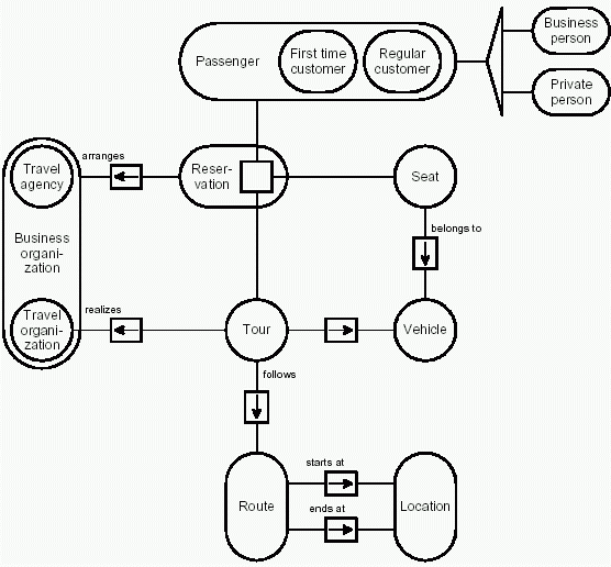
Figure C.3 shows an entity relationship diagram representing the structure of the information, which is found when looking at the storage labeled "reservations" and "customer data" which both the "reservation system" and the "travel organizations" can access (see figure C.1). In the middle of the diagram, we see a rounded node labeled "reservations" which represents the set of all reservations being stored in system. Such a reservation is defined by a customer booking a certain tour, allocating a certain seat in a certain vehicle. The tour will follow a certain route, starting at some location and ending at some location. Looking at the passengers, first time customers are distinguished from regular customers. Independent from that, passengers can also be partitioned into business persons and private persons. The system also stores information about the organization which has arranged a reservation and which travel organization realizes which tour.
In entity relationship diagrams, round nodes visualize different sets of entities each being of a certain type. The sets in the example are passengers, business men, tours, vehicles etc. Each of them is defined by a set of attributes according to its type. Most elements of a set have one or more relations to elements of another or also the same set of elements. For instance, each route has one location to start at and one location to end at. Each relationship, i.e. each set of relations between two sets of entities being of a certain type, is represented by a rectangular node connected to the nodes representing the sets of entities participating in the relationship. So there is one rectangle representing the "start at" relationship and another representing the "ends at" relationship. Annotations beside the rectangle can be used to specify the predicate by an expression using natural language, which defines the relationship.
The cardinality of a relationship expresses the number of relations of a certain type one entity may participate in. Arrows respectively small numbers attributing the relationship nodes represent the cardinality. A bidirectional arrow symbolizes a one-to-one assignment of entities. A unidirectional arrow symbolizes that multiple elements of one entity set may be related to one single entity. Looking at our example, the arrow pointing from "seats" to "vehicles" expresses that every seat belongs to exactly one vehicle and that every vehicle contains multiple seats.
If one entity node contains multiple sub-nodes, this entity node represents the union of the entity sets being enclosed. Typically the elements of the union share a common type, an abstraction characterizing the elements of all subsets. For instance in the example "first time customers" and "regular customers" define the set of "passengers". But we can also distinguish "business persons" from "private persons", also the result of another true partitioning of "passengers". To avoid visual confusion caused by multiple containment nodes crossing each other, those unrelated partitions are symbolized using a longish triangle.
Sometimes it is helpful to interpret the elements of some relationship as entities itself, which by itself may participate further relations. Those abstract entities may have no direct physical counterpart. They are the objectification of some concrete fact, a statement about the relation among some given entities. A typical example is the relationship labeled "reservation" between the sets of "passengers", "tours" and "seats". Each element of that relationship embodies an entity itself -- a reservation, which is arranged by some travel agency or travel organization.
Entity relationship diagrams may not only be used to visualize the structure of the information stored in technical systems. They also can help to get some understanding of new application domains by providing an overview of the relations between its concepts.
 |
Apache Modeling Portal 2004-10-29 |