The Quick Introduction to FMC should give you an idea of what FMC is about and what it looks like. The main ideas of FMC are explained using one continuous example. It is a writ instead of slides collection so it is easier to understand the coherences. This text is also available as download (408.58kB).
FMC is the acronym for "Fundamental Modeling Concepts", primarily a consistent and coherent way to think and talk about dynamic systems. It enables people to communicate the concepts and structures of complex informational systems in an efficient way among the different types of stakeholders. A universal notation originating from existing standards, easy to learn and to apply, is defined to visualize the structures and to communicate in a coherent way. In contrast to most of the visualization and modeling standards of today it focuses on human comprehension of complex systems on all levels of abstraction by clearly separating conceptual structures from implementation structures. FMC is based on strong theoretical foundations, has successfully been applied to real-life systems in practice (at SAP, Siemens, Alcatel etc.) and also is being taught in software engineering courses at the Hasso Plattner Institute for Software Systems Engineering.
This quick introduction will give you an idea of what FMC is all about by presenting you the key concepts starting with a small but smart example. Following the example, you will learn about FMC's theoretical background, the notation and hopefully get a feeling about the way FMC helps to communicate about complex systems. At first glance you might find the example even trivial, but keep in mind that this little example presented here may be the top-level view of a system realized by a network of hundreds of humans and computers running a software built from millions of lines of code. It would hardly be possible to efficiently develop such a system without efficient ways to communicate about it.
The example describes different aspects of a travel agency system. Starting with a top level description of the system, we will shift our focus towards implementation, while still remaining independent from any concrete software structures. Hence, do not expect to see UML class diagrams, which doubtlessly might be helpful to represent the low-level structures of software systems.
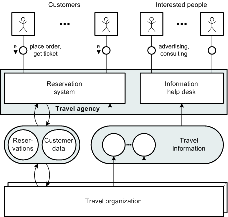
Figure 1 shows a block diagram representing a model of the static compositional structure of a travel agency system and its environment. In the upper part of the block diagram several rectangles are shown, each containing the stylised figure of a human. The left group are customers of the travel agency interacting with the reservation system. Reservation orders can be placed, which are transmitted to the corresponding travel organizations, while the customers are issued their tickets. To the right are those persons looking for travel information using the information help desk. This information is provided by the different travel organizations and is stored in a location symbolized by the big rounded rectangle labeled "travel information".
This block diagram, like any block diagram, represents a real or at least imaginable real informational system. The system described is no more abstract than anything else we consider to be real. Looking at the system we see components, artifacts of our mind, which relate to tangible distinguishable physical phenomena. This view applies to our perception of technical devices and living beings as well as of any composite structure. Thus, an informational system can be seen as a composition of interacting components called agents. Each agent serves a well-defined purpose and communicates via channels and shared storages with other agents. If an agent needs to keep information over time it has access to at least one storage where information can be observed. If the purpose is not to store but to transmit information the agents are connected via channels.
 Figure 1: Block diagram - Travel agency system
Agents are drawn as rectangular nodes, whereas locations are symbolized as rounded nodes. In particular, channels are depicted as small circles and storages are illustrated as larger circles or rounded nodes. Directed arcs symbolize whether an agent can read or write information from or to a storage.
In the example, the arcs directed from the nodes labeled "travel organization" to the storage node labeled "travel information" symbolize that the travel organizations write the travel information. Correspondingly the arc directed from the storage node labeled "travel information" to the agent node labeled "information help desk" symbolizes that the help desk reads the travel information. If an agent can modify the contents of a storage regarding its previous contents, it is connected via a pair of opposed bound arcs, called modifying arcs. The access of the reservation system and the travel organization to the customer data storage is an example.
If communication is possible in both directions, the arcs connecting the agents via a channel may be undirected. Looking at the example, communication between the help desk and people interested in some information is visualized that way. A very special but common variant of this case is a request/response channel where a client requests a service from another agent and after a while gets its response. To express which side is requesting the service a small arrow, labeled "R" for request and pointing from client to server, is placed beside the node symbolizing the channel. Examples are the channels between the customers and the reservation system.
Informational systems are dynamic systems. By looking for some time at the channels and locations that are used to store, change, and transmit information their behaviour can be observed. Extended Petri nets are used to visualize the behaviour of a system on a certain level of abstraction corresponding to a block diagram.
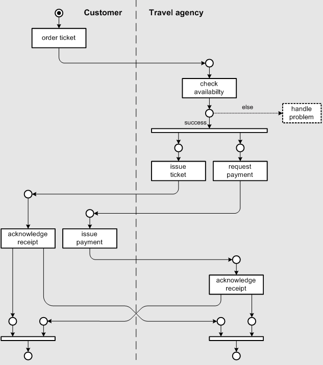
 Figure 2: Petri net - Buying a ticket
Figure 2 shows a Petri net describing the causal structure of what can be observed on the channel between the travel agency and one of its customers in our example. Buying a ticket starts with the customer ordering a ticket. Then the travel agency checks the availability and in case this step is successful, a ticket may be issued to the customer concurrently with a request of payment. The customer is expected to issue the payment and when both sides have acknowledged the receipt of the money or the ticket, respectively, the transaction is finished.
Petri nets describe the causal relationship between the operations performed by the different agents in the system. Each rectangle is called a transition and represents a certain type of operation. The transitions are connected via directed arcs with circular nodes called places. Places can be empty or marked, which is symbolized by a black dot (token). The behaviour of the system can now be simulated by applying the following rule to the Petri net: Whenever there is a transition with all its input places marked and all its output places unmarked this transition may fire, meaning the operation associated with the transition is performed. Afterwards all input places of the transition are empty and all its output places are marked.
Looking at the Petri net shown in Figure 2, in the beginning only the transition labeled "order ticket" may fire. This means the first operation in the scenario described will be the customer ordering a ticket. Because only the initial marking of a Petri net may be shown in a printed document, it is necessary to process the net by virtually applying the firing rules step by step until you get an understanding of the behaviour of the system. This is very easy as long as there is only one token running through the net.
Common patterns are sequences of actions, loops, and conflicts. A conflict is given if multiple transitions are enabled which are connected to at least one common input place. Because the marking of that input place cannot be divided, only one of the transitions may fire. In many cases a rule is given to solve the conflict. In those cases predicates labeling the different arcs will help to decide which transition will fire. For example, different actions have to be taken depending on the outcome of the availability check. If the check was successful the travel agency will issue the ticket and request payment.
In our example issuing the ticket and payment should be allowed to happen concurrently. Using Petri nets it is possible to express concurrency by entering a state where multiple transitions may fire concurrently. In the example we introduce concurrency by firing the unlabeled transition, which has two output places. Afterwards both transitions, the one labeled "issue ticket" and the one labeled "request payment", are allowed to fire in any order or even concurrently. The reverse step is synchronization, where one transition has multiple input places that all need to be marked before it is enabled.
Using refinement it is possible to describe single transitions or parts of the Petri net in more detail. Furthermore, by refining the compositional structure of the system or by introducing a new aspect additional Petri nets may become necessary to describe the interaction of the new components.
Looking at dynamic systems we can observe values at different locations, which change over time. In our model, agents are responsible for those changes which have read and write access to these locations forming a commonly static structure, which is shown in a block diagram. Petri nets give us a visual description of the agent's dynamic behaviour. To describe the structure and repertoire of information being passed along channels and placed in storages entity relationship diagrams are used.
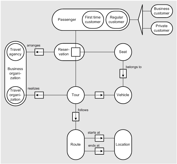
Figure 3 shows an entity relationship diagram representing the structure of the information, which is found when looking at the storage labeled "reservations" and "customer data" which both the "reservation system" and the "travel organizations" can access (see Figure 1). In the middle of the diagram we see a rounded node labeled "reservations" representing the set of all reservations stored in the system. Such a reservation is defined by a customer booking a certain tour, allocating a certain seat in a certain vehicle. The tour will follow a certain route starting at some location and ending at some other location. Looking at the passengers first time customers are distinguished from regular customers. Independently, passengers can also be partitioned into business and private travellers. The system also stores which organization has arranged which reservation and which travel organization realizes which tour.
 Figure 3: Entity relationship diagram - Tour reservations
Using entity relationship diagrams round nodes visualize different sets of entities, each being of a certain type. The sets in the example are passengers, business people, tours, vehicles etc. Each of them is defined by a set of attributes according to its type. Most elements of a sets have one or more relations to elements of another or also the same set of elements. For instance, each route has one location to start at and one location to end at. Each relationship, i.e. each set of relations between two sets of entities of a certain type, is represented by a rectangular node connected to the nodes representing the sets of entities participating in the relationship. Thus, there is one rectangle representing the "starts at" relationship and another representing the "ends at" relationship. Annotations besides the rectangle can be used to specify the predicate, an expression using natural language which defines the relationship.
The cardinality of a relationship expresses the number of relations of a certain type one entity may participate in. Arrows or small numbers, respectively, attributing the relationship nodes represent the cardinality. A simple arrow symbolizes the direction of a functional relationship. Each element of the set the arrow emanates from is associated to one element of the related set. Looking at our example the arrow pointing from "seats" to "vehicles" expresses that every seat belongs to exactly one vehicle. A bi-directional arrow symbolizes a one-to-one assignment of entities.
If one entity node contains multiple sub-nodes it represents the union of the entity sets enclosed. Typically the elements of the union share a common type, an abstraction characterizing the elements of all subsets. For instance, in the example "first-time customers" and "regular customers" define the set of "passengers". But we can also distinguish "business customers" from "private customers", which are the result of another true partitioning of "passengers". To avoid visual confusion caused by multiple containment nodes crossing each other these unrelated partitions are symbolized using a longish triangle.
Sometimes it is helpful to interpret the elements of a relationship as entities themselves which may participate in further relations. Such abstract entities may have no direct physical counterpart. They are the reification of some concrete fact, a statement about the relation among some given entities. A typical example is the relationship labeled "reservation" between the sets of "passengers", "tours", and "seats". Each element of that relationship embodies an entity itself - a reservation arranged by some travel agency or travel organization.
Entity relationship diagrams may not only be used to visualize the structure of the information stored in technical systems. They can also help to gain some understanding of new application domains by providing an overview of the relations between its concepts.
So far, the system has been described on a very abstract level only reflecting its purpose. The implementation of most components is still undefined. We see a high-level structure that also could be explained with a few words. Looking at the block diagram (Figure 1) we only learn that the customers and interested people are expected to be humans. Nothing is said about how the reservation system, the help desk, or the travel organization are implemented, what the stored information looks like, whether it will be an office with friendly employees answering questions and distributing printed booklets or an IT system accessible through the Internet. All that is undefined on the present level of abstraction.
Nevertheless, the model shows a very concrete structure of the example system. The system structure has been made visual, which highly improves communication efficiency. There is some meaningful structure you can point to, while talking about it and discussing alternatives. This would be inherently impossible if the real system does not exist yet or the system just looks like a set of technical low-level devices that could serve any purpose.
By refining the high-level structure of the system, while considering additional requirements, a hierarchy of models showing the system on lower levels of abstraction is created. Again, the system description can be partitioned according to the three fundamental aspects that define every dynamic system - compositional structure, behaviour, and value structures. By making the relationship between the different models visible (using visual containment and descriptive text) comprehension of the systems is maintained over all levels of abstraction. With this approach it is possible to prevent the fatal multiplication of fuzziness in communicating about complex structures without anything to hold on to.
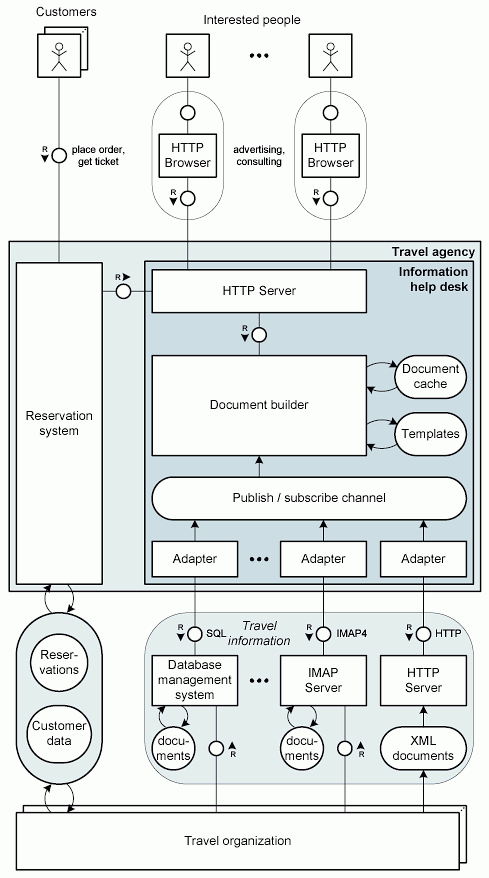
Figure 4 shows a possible implementation of the information help desk and the storage holding the travel information. The storage turns out to be implemented as a collection of database, mail, and web servers used by the different travel organizations to publish their documents containing the travel information. The information help desk contains a set of adapters used to acquire the information from the different data sources. The core component of the help desk is the document builder. It provides the documents assembled from the collected information and from a set of predefined templates to a web server. People interested in travel agency services can read the documents from this web server using a web browser. It is not obvious that the reservation system now has to request travel information from the information help desk instead of getting it itself. This is an example for non-strict refinement.
We could continue to describe the dynamics and value structures on that level, afterwards refining or introducing new aspects one more time and so on. We will not do this here. When to stop this iteration cycle depends on the purpose of your activities: Maybe you are you going to create a high-level understanding of the system's purpose, maybe you are discussing design alternatives of the systems architecture, or estimating costs, or what have you.
 Figure 4: Block diagram - Implementation of the information help desk
Knowing the system's structure presented in Figure 1 it is quite easy to understand the more complex lower-level structure presented now. To ease comprehension components from a higher-level system view should be projected into the lower-level system view whenever possible. In case implementation is done by simple refinement the result will be a containment hierarchy between the nodes representing components of different levels of abstraction. Without doubt it would be much harder to understand the example system had it been introduced on the level of adapters, mail servers, and browsers. It would have been nearly impossible to create a common understanding without any illustrations at all.
FMC focuses on human comprehension of informational systems. The key is the strict separation of a very few fundamental concepts which can always be distinguished when communicating about informational system. Generally one should distinguish between
FMC provides the concepts to create and visualize didactic models enabling people to share a common understanding of a system's structure and its purpose. Therefore FMC helps to reduce cost and risk in the handling of complex systems.